Now that the dry assembly of the fuselage is disassembled, I moved on to the scariest job so far: drilling the holes in C2 and C3 for the wing pins. A great deal of the documentation is dedicated to this topic, but in the end the process is not that complicated.
Ultimately, this is how I did the job:
- I decided to keep C2 and C3 clamped together as they were, with the 65 mm spacers in place. In other words, exactly as they had been positioned on the strongback.
- I drilled 22 mm holes because I am going to make brass or bronze bushings. Yes, I know that is heavier, but I do not want direct aluminium-to-steel contact.
This is how I set up and checked the reference system:
- The strongback was perfectly levelled, and I verified it again.
- I checked that C3 and C2 were level in the assembly. They were perfect. That gave me a straight line to use as a reference, so if the holes were drilled from that reference, the wing would sit level in the fuselage.
- I checked and marked the centreline on C3 and C2.
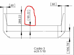
After these checks, I finally removed the C2/C3 assembly from the strongback and marked the holes on C3, as stated in the plans. I used the 93 mm dimension from the plan and drilled the holes at a 940 mm spacing, equidistant from the previously marked centreline. Before drilling, I double checked the marks with my false spar assembly.
×
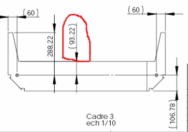
C3 with the 93 mm reference used to locate holes.
×
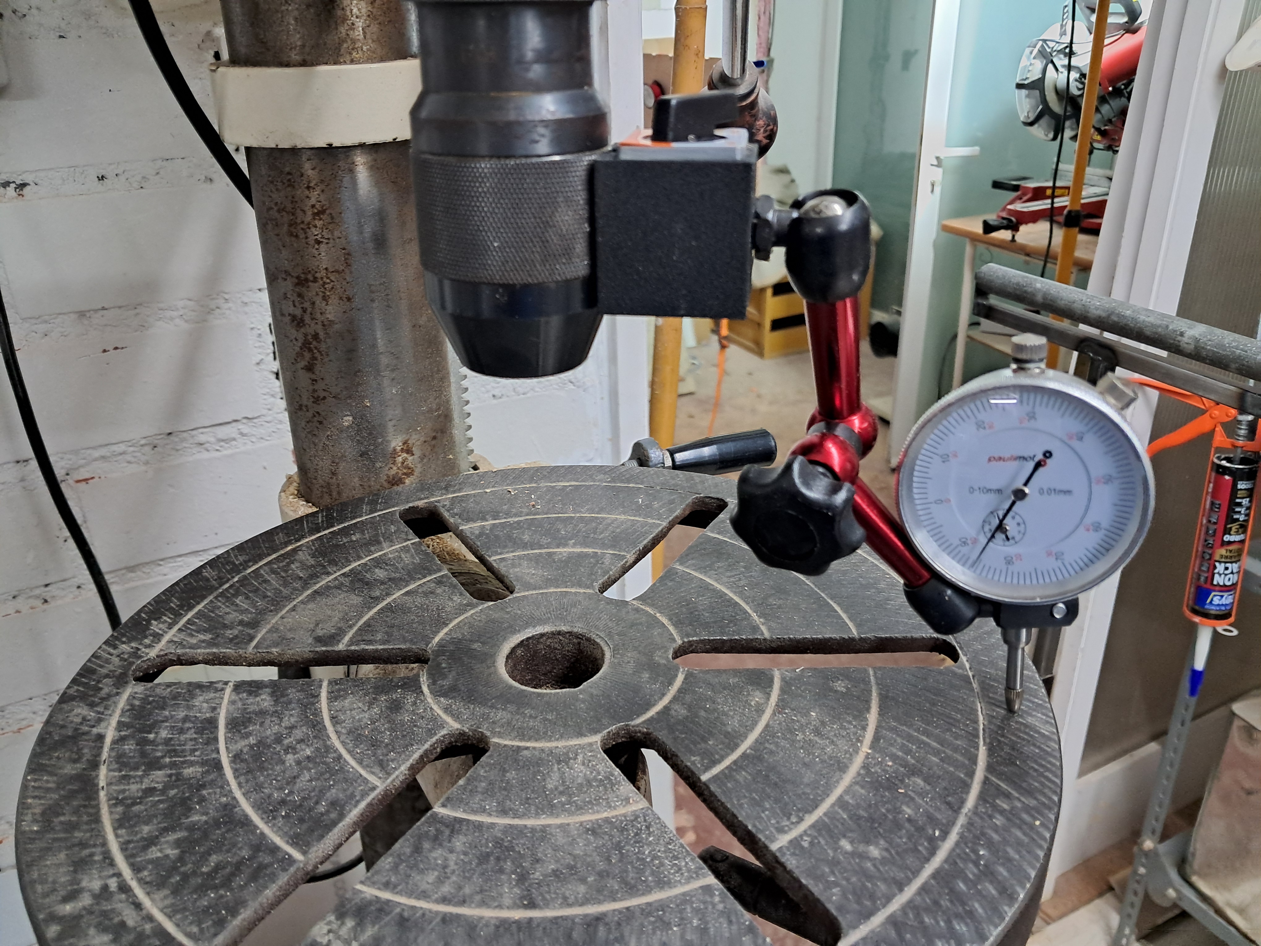
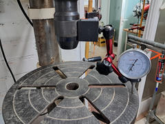
Levelling the drill press table to make sure the holes are drilled straight.
×
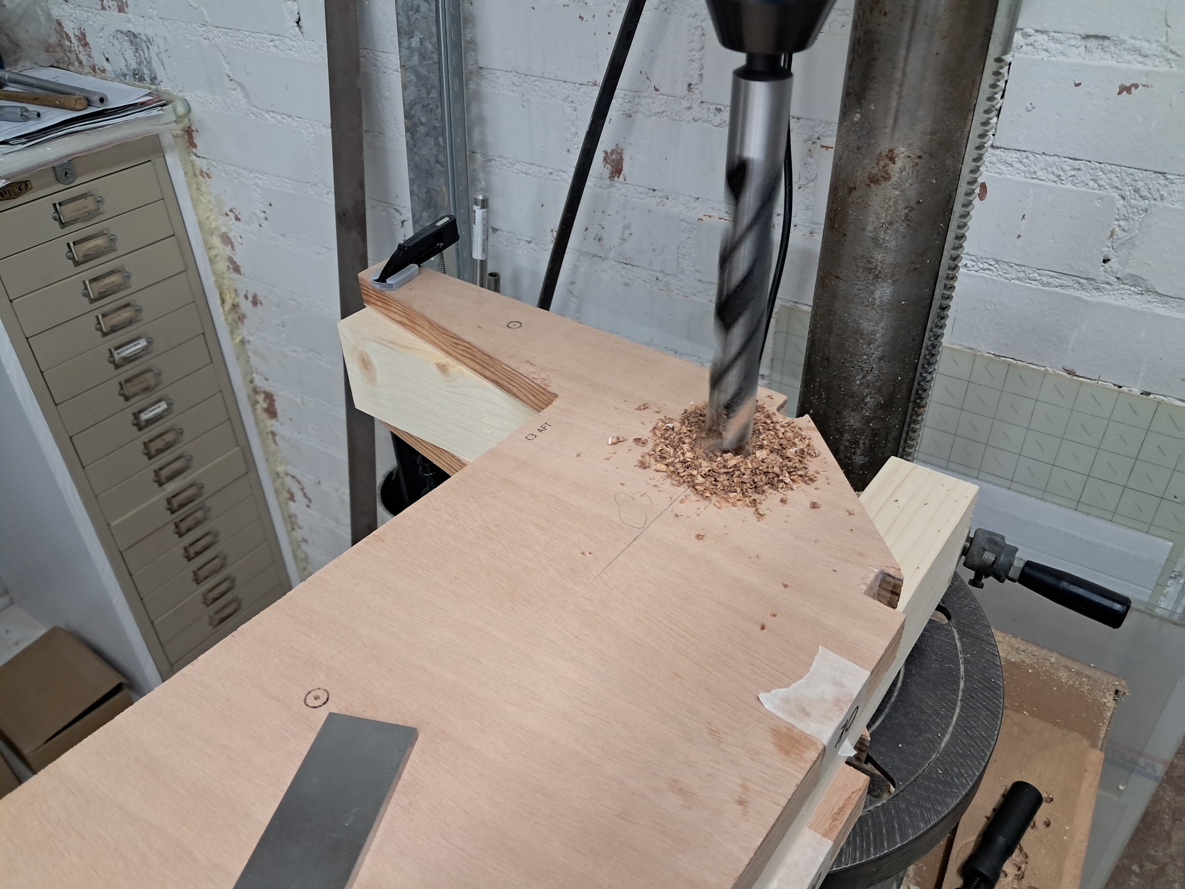
Drilling the first 22 mm wing pin hole through the C2/C3 assembly.
×
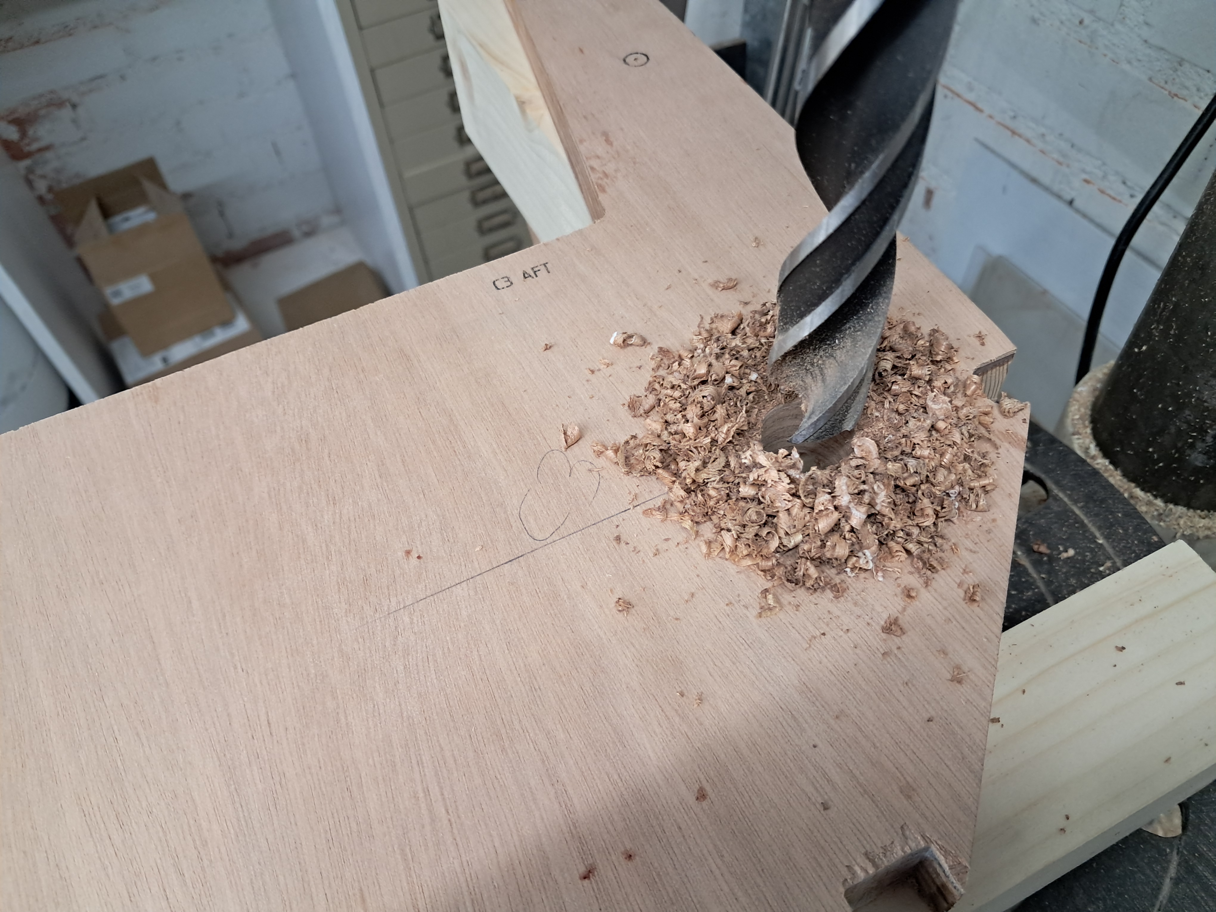
Close-up of the auger bit cutting the wing pin hole. I advanced slowly and kept checking alignment.