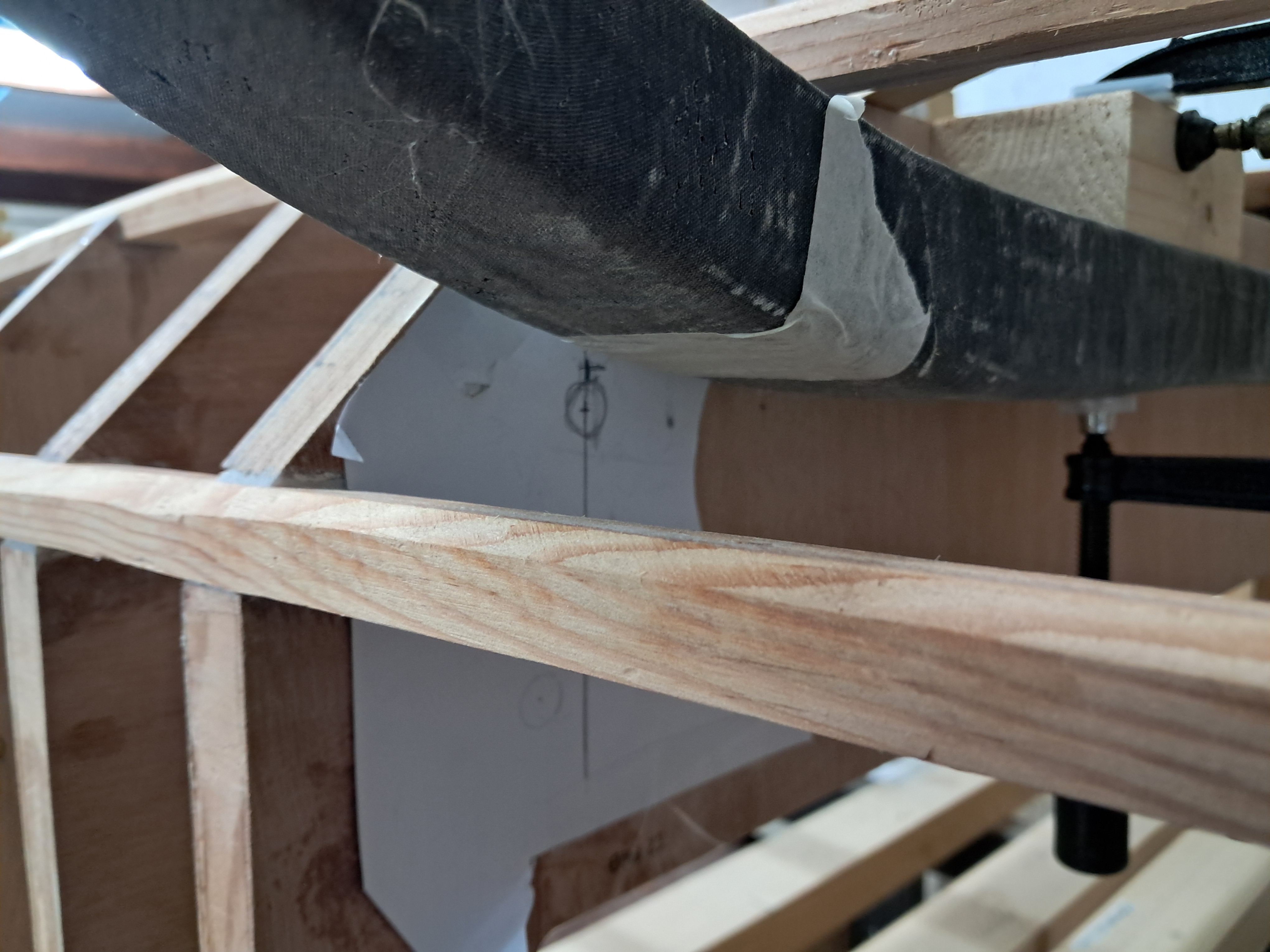
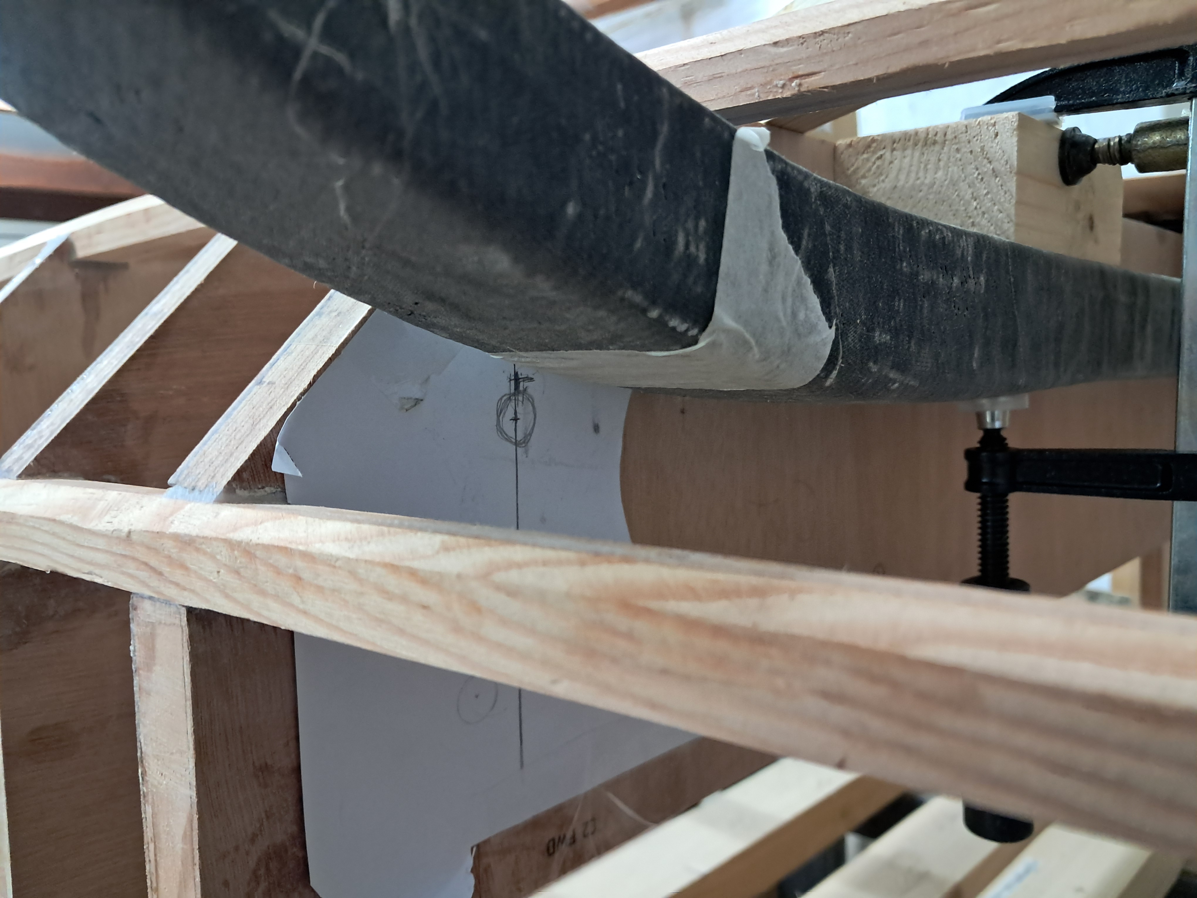
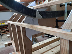
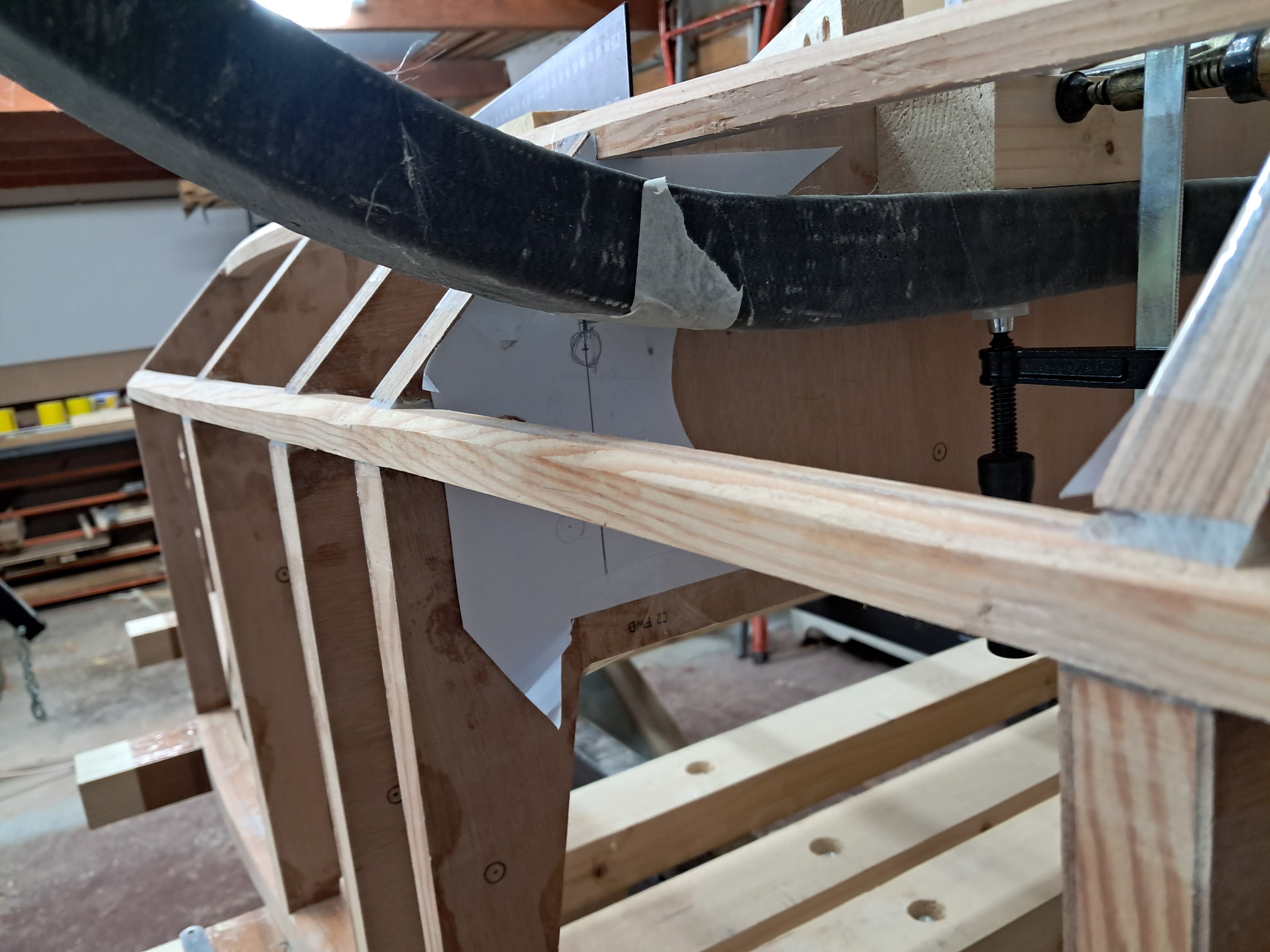
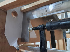
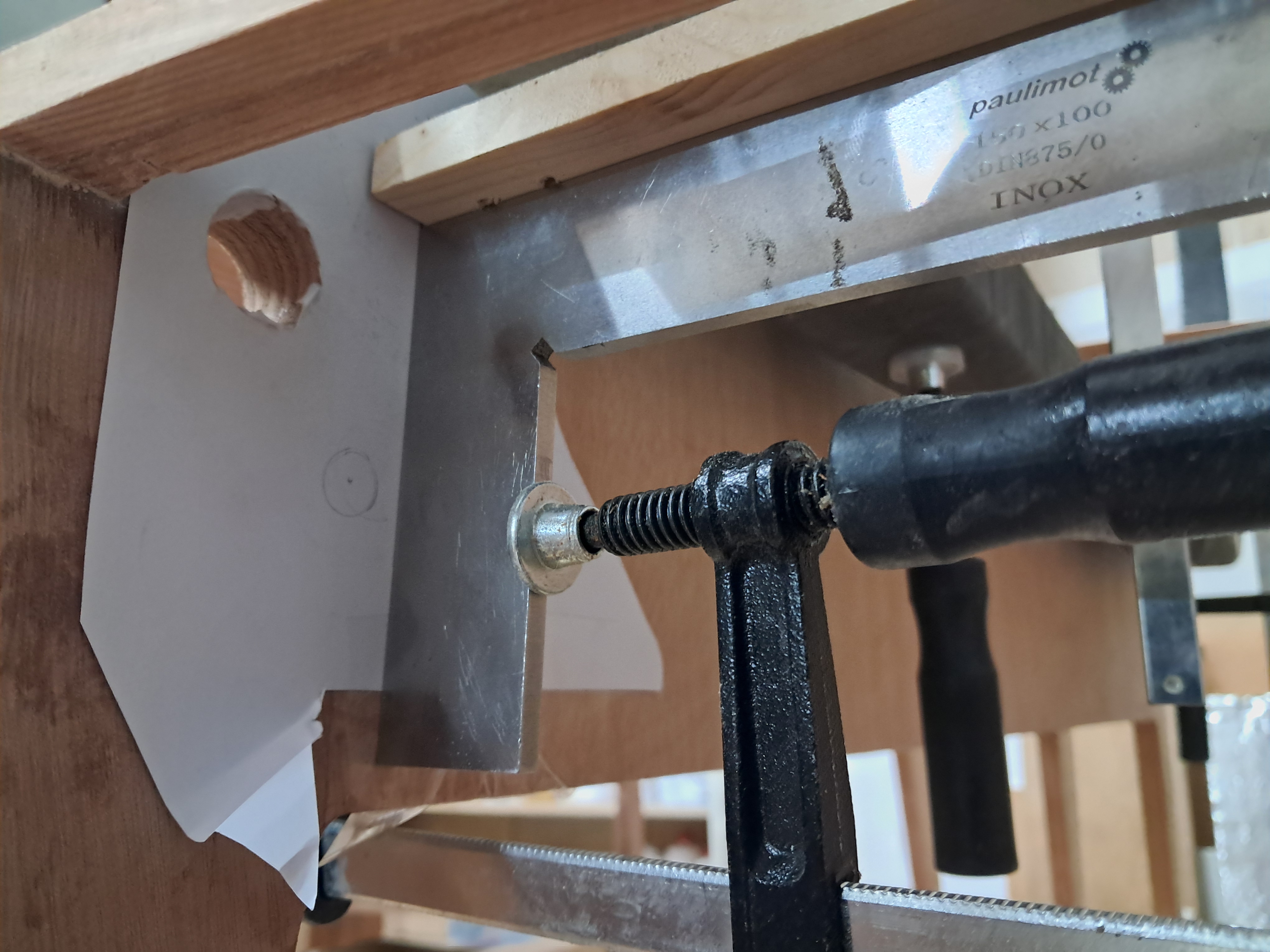
I made a second attempt at locating the landing gear to mark the holes for the pins in the bulkheads.
After a discussion with Serge, the pins will run on a bias and not perpendicular to the bulkheads or the longitudinal axis.
Not sure why I initially wanted the pin to be perpendicular... we humans think too much in rectangles, really.
Opening up to having the pin as per plans(!) on a bias solves the issue of placing the bushing bore in the bulkhead corners.
After a bit of back and forth, all four hole positions are marked.
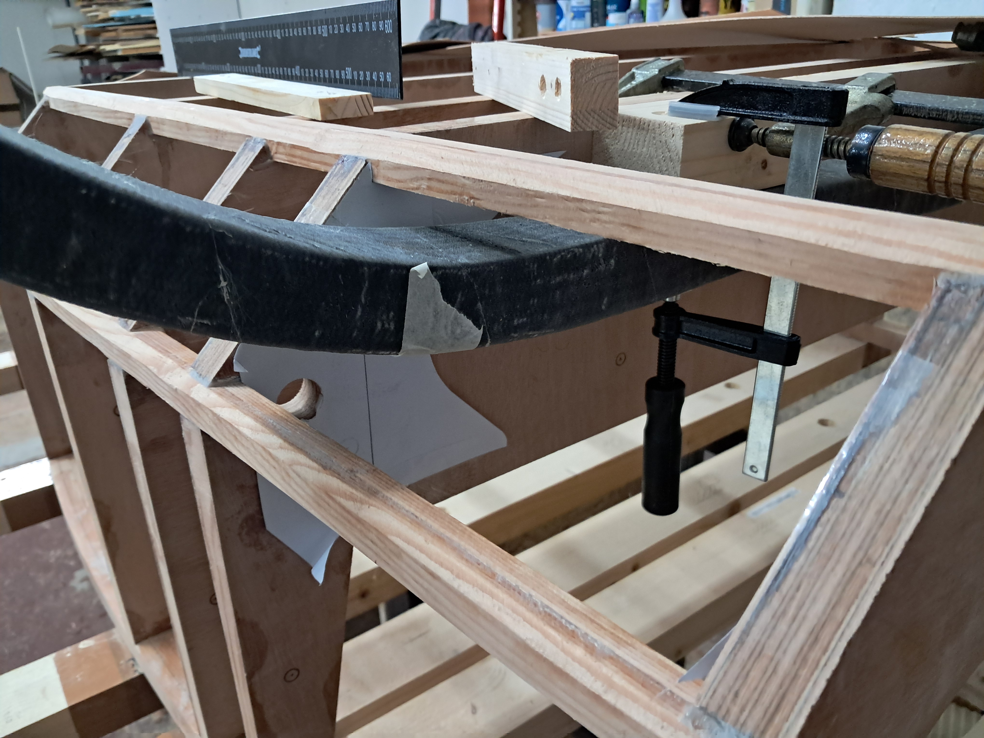
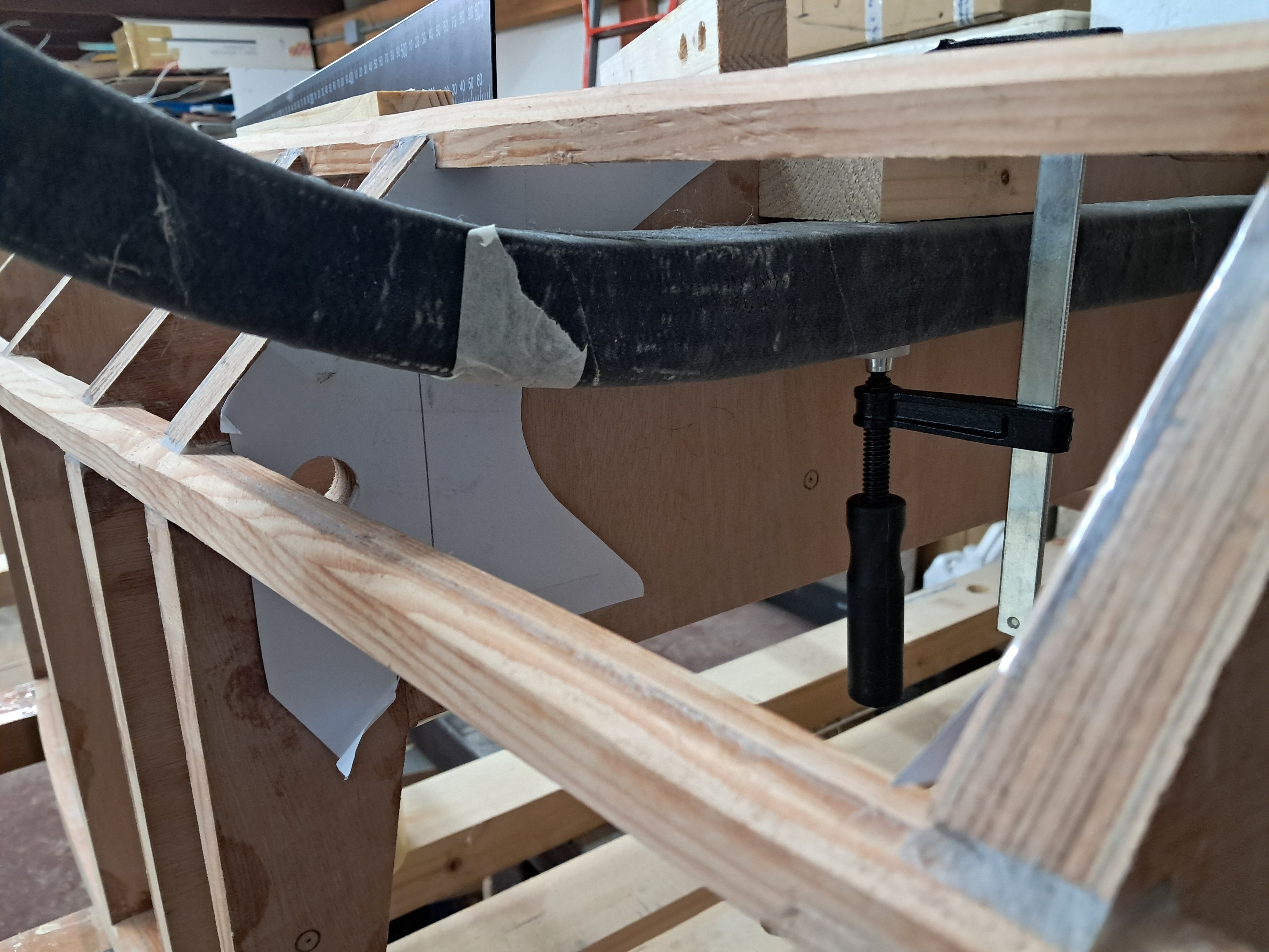
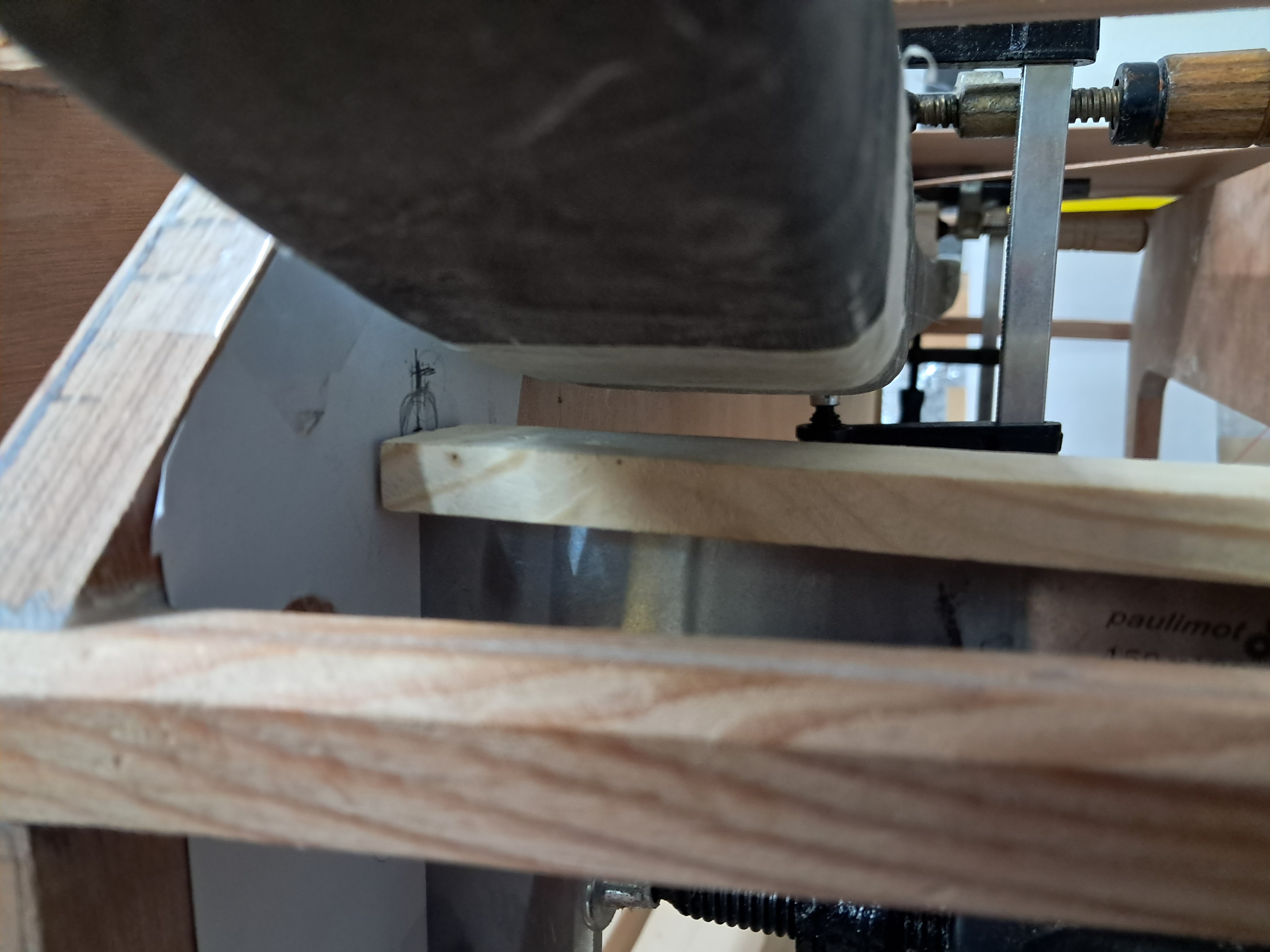
Second attempt at locating the landing gear: the leaf clamped between C1 and C2.
×
Second attempt at locating the landing gear: the leaf clamped between C1 and C2.
The gear leaf in position, the paper template on C2 behind it.
×
The gear leaf in position, the paper template on C2 behind it.
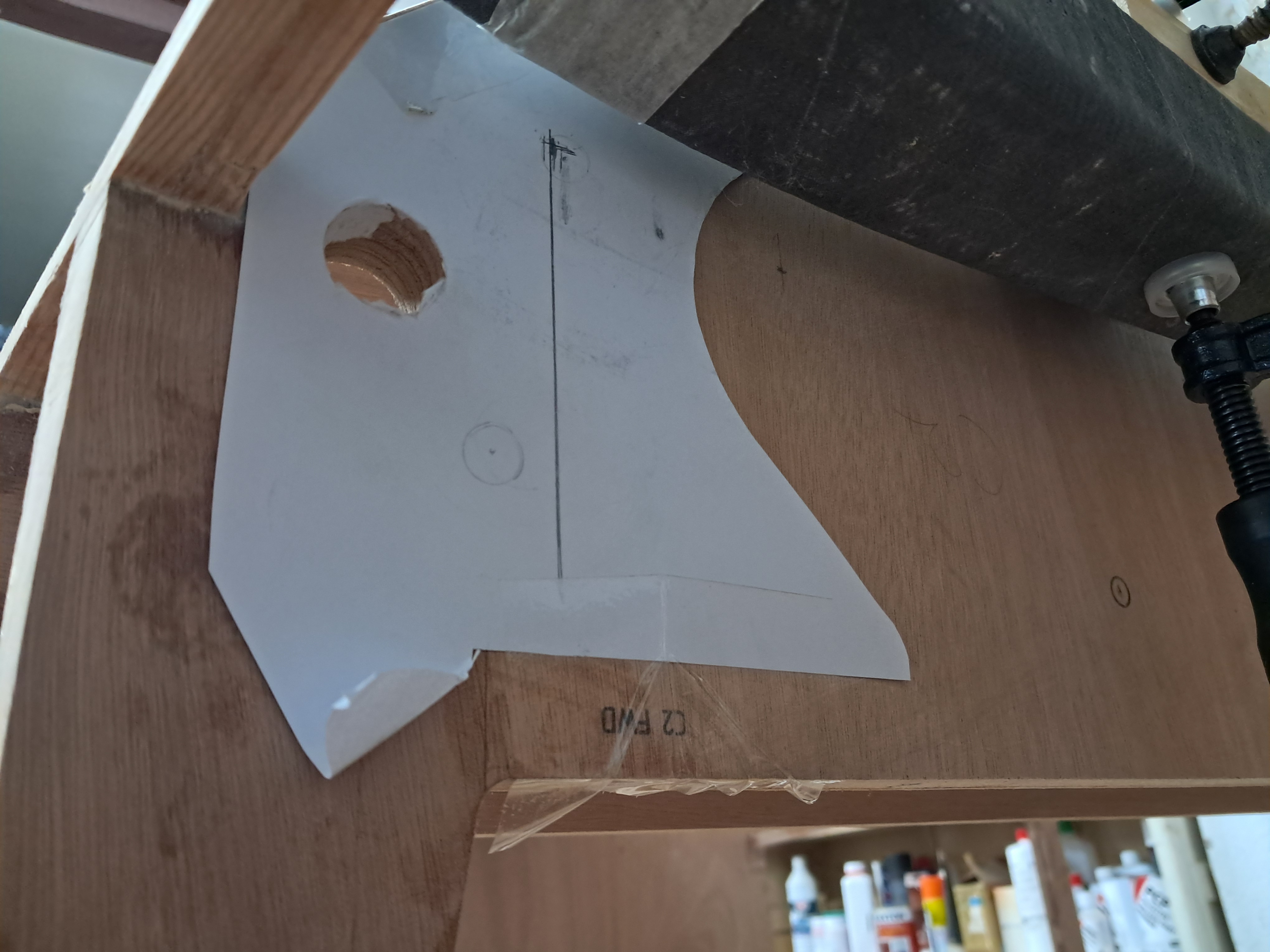
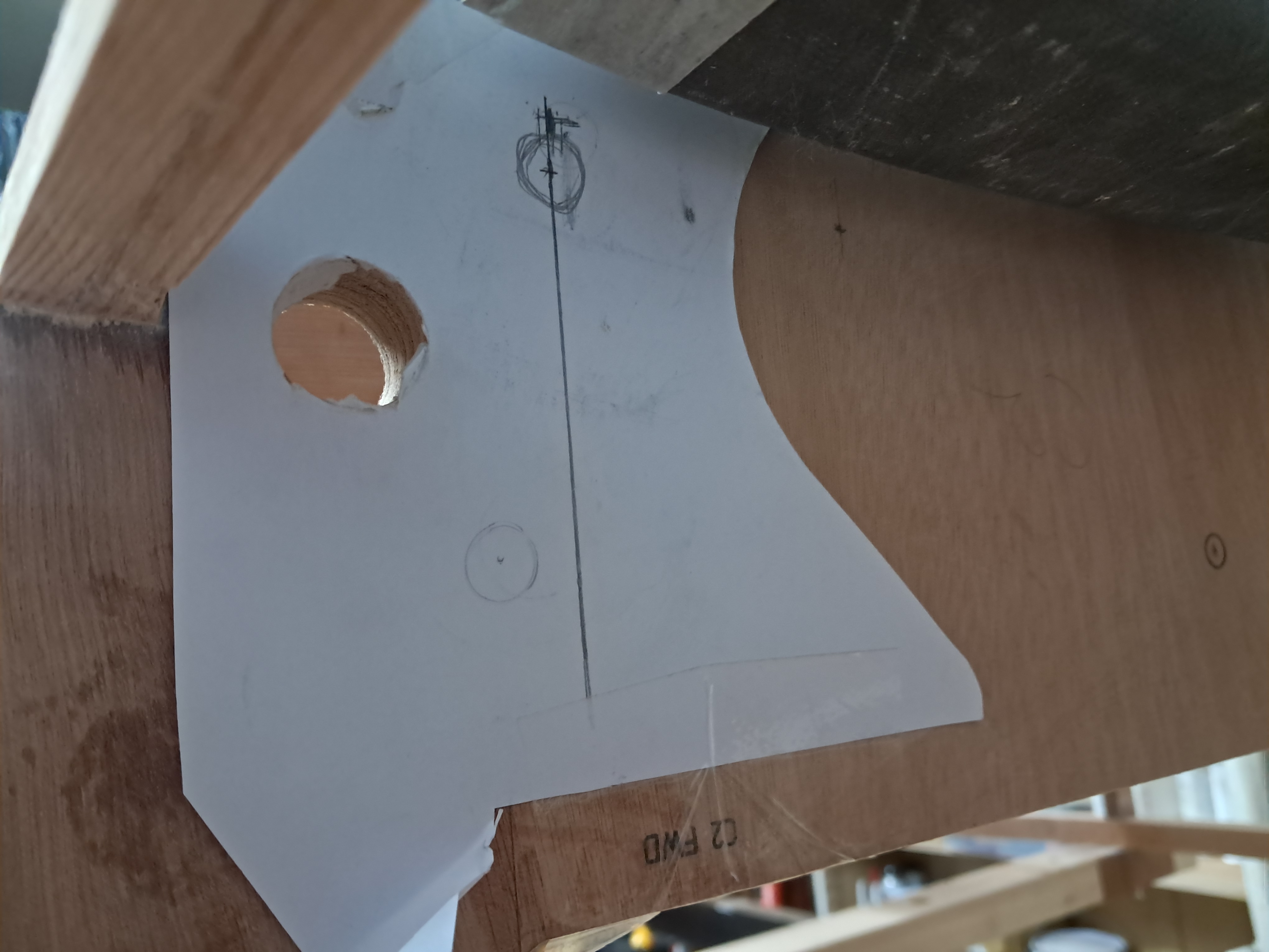
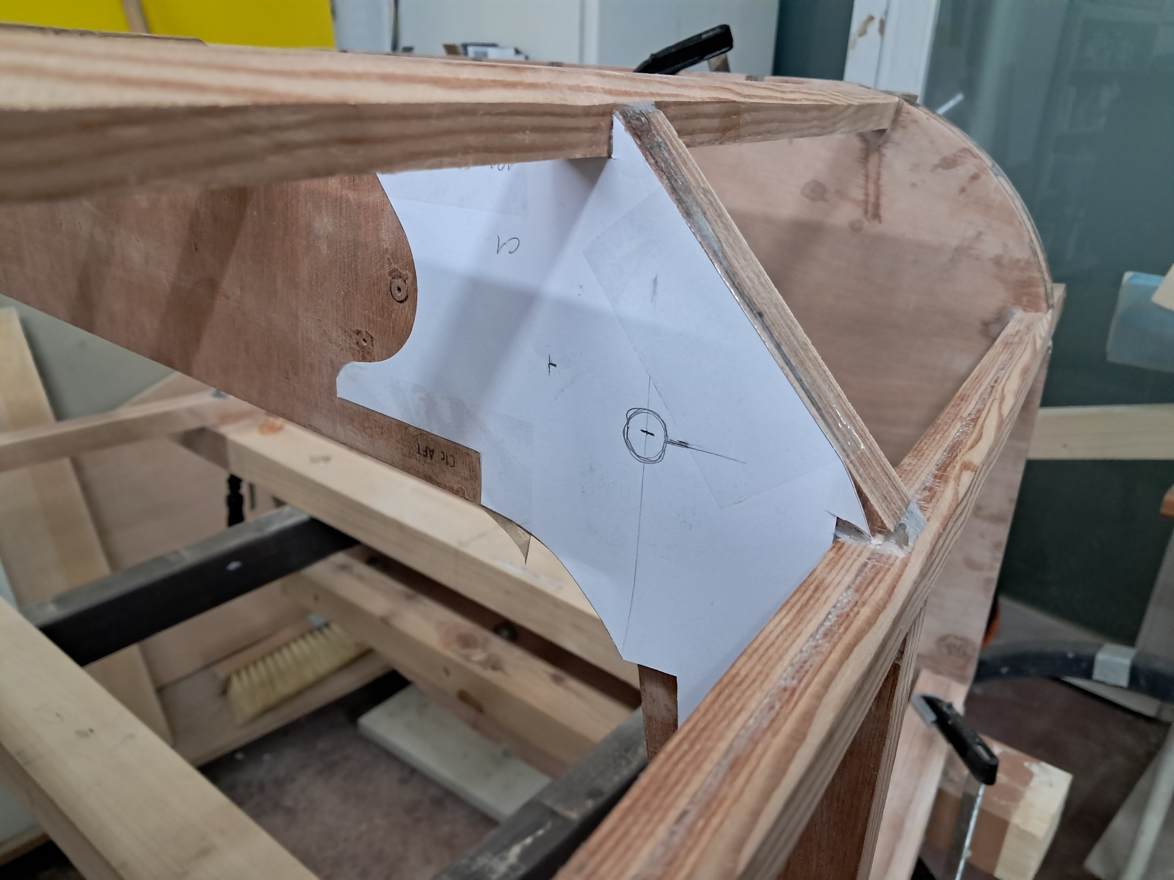
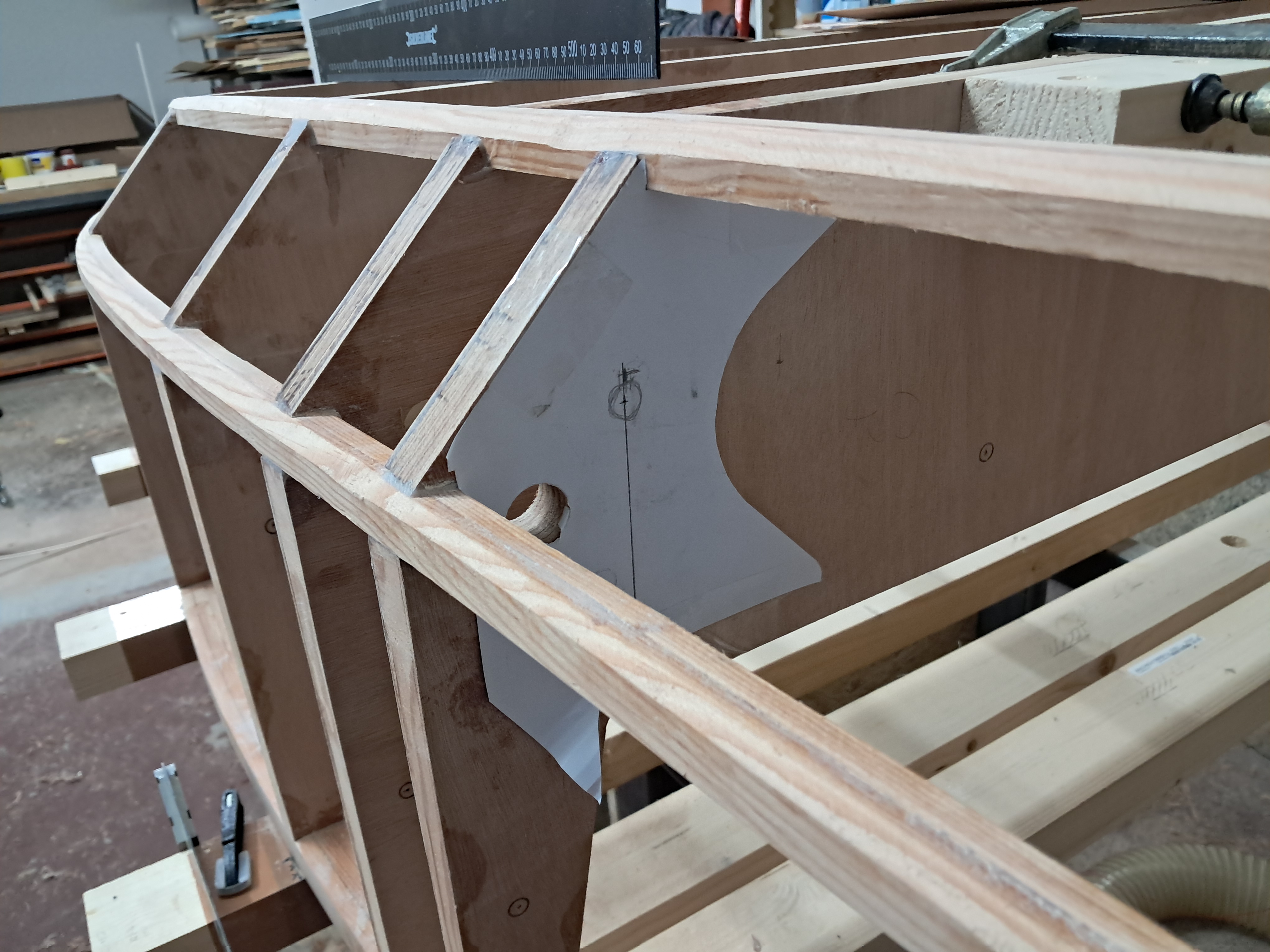
Paper template on C2 with the pin axis marked. The pins will run at an angle, not perpendicular to the bulkheads.
×
Paper template on C2 with the pin axis marked. The pins will run at an angle, not perpendicular to the bulkheads.
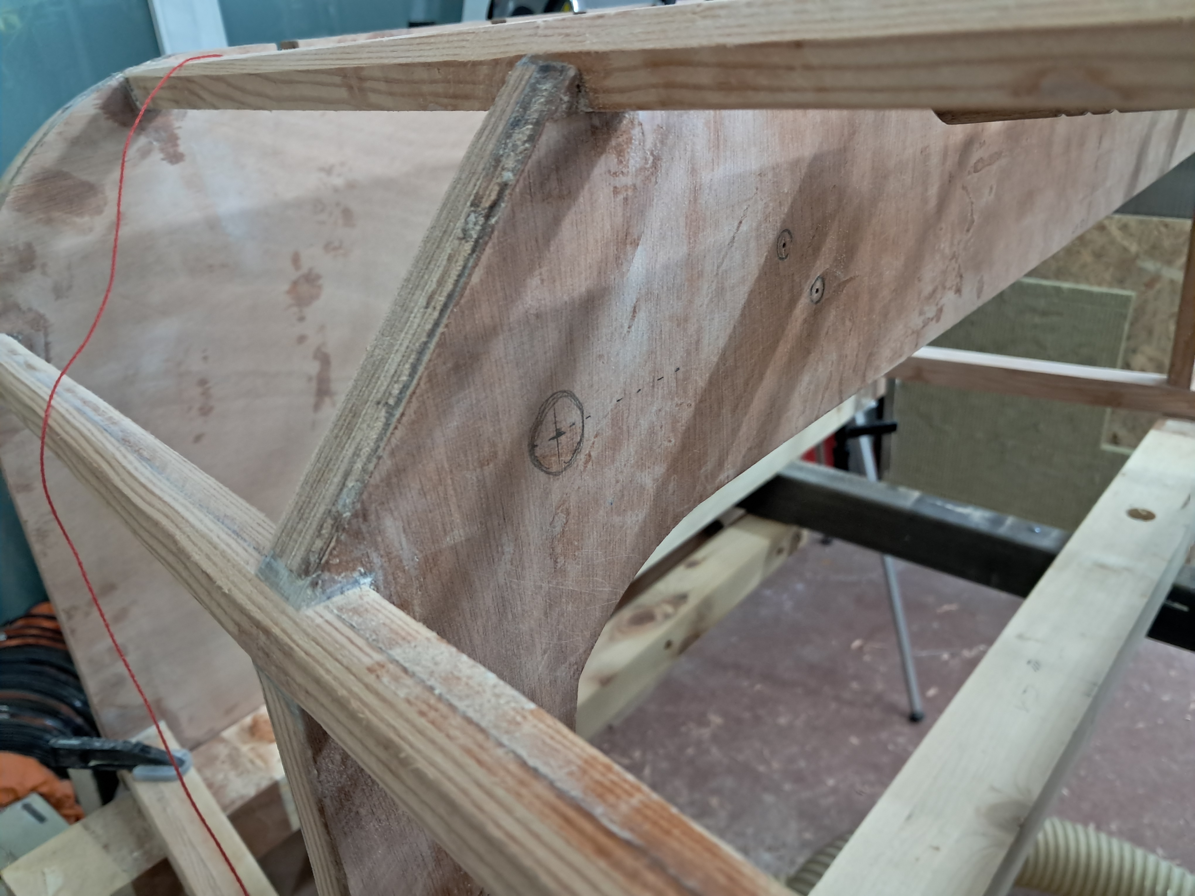
The marked pin position on the template, close to the bulkhead corner.
×
The marked pin position on the template, close to the bulkhead corner.
The saddle on the leaf lines up with the marked pin position.
×
The saddle on the leaf lines up with the marked pin position.
Same view from slightly further back.
×
Same view from slightly further back.
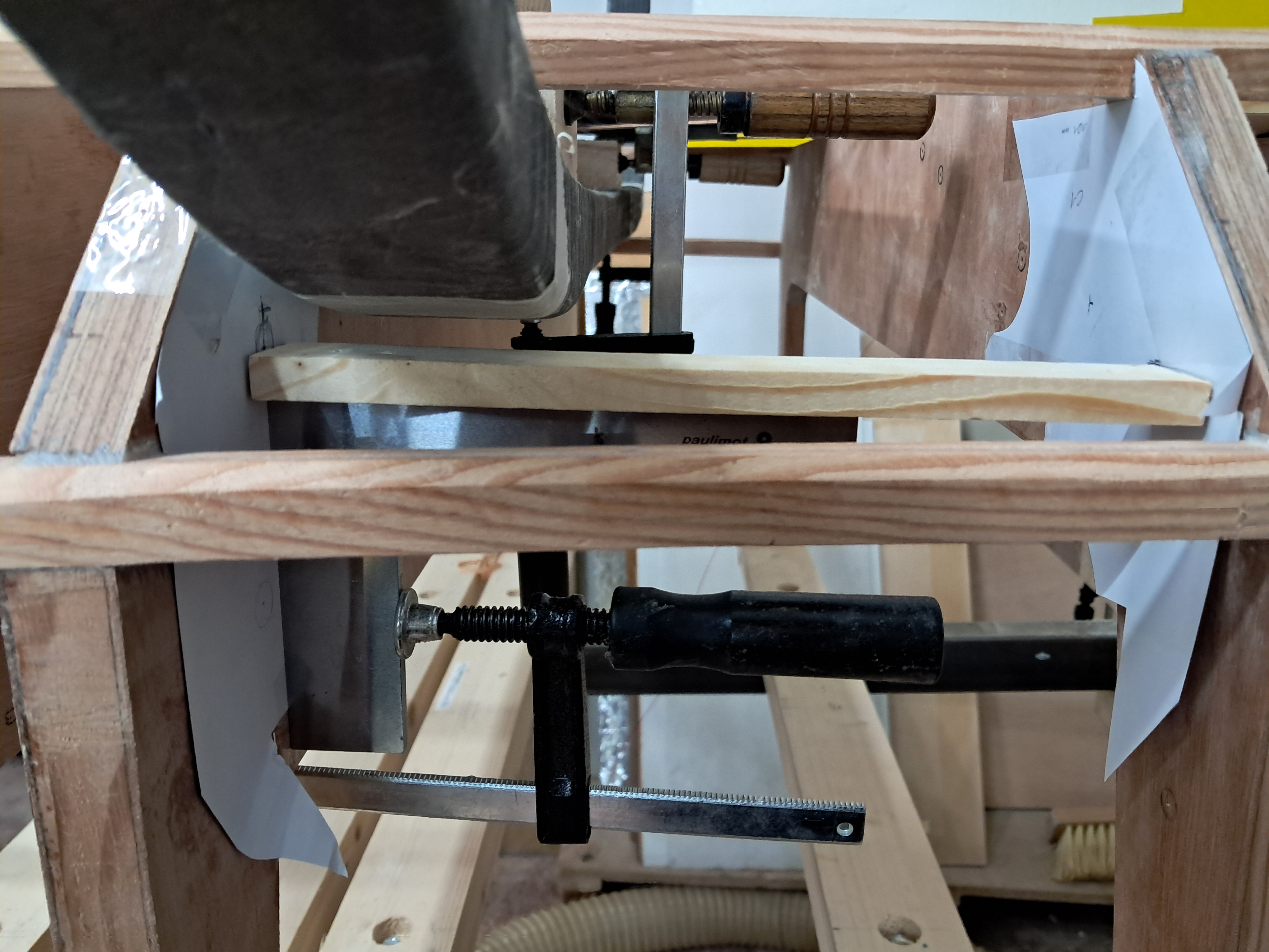
Overview of the setup: leaf, template and clamps.
×
Overview of the setup: leaf, template and clamps.
A machinist square clamped on to transfer the pin axis to the bulkhead.
×
A machinist square clamped on to transfer the pin axis to the bulkhead.
A straight board spans the bay as a reference for the alignment.
×
A straight board spans the bay as a reference for the alignment.
The transfer setup seen from the side.
×
The transfer setup seen from the side.
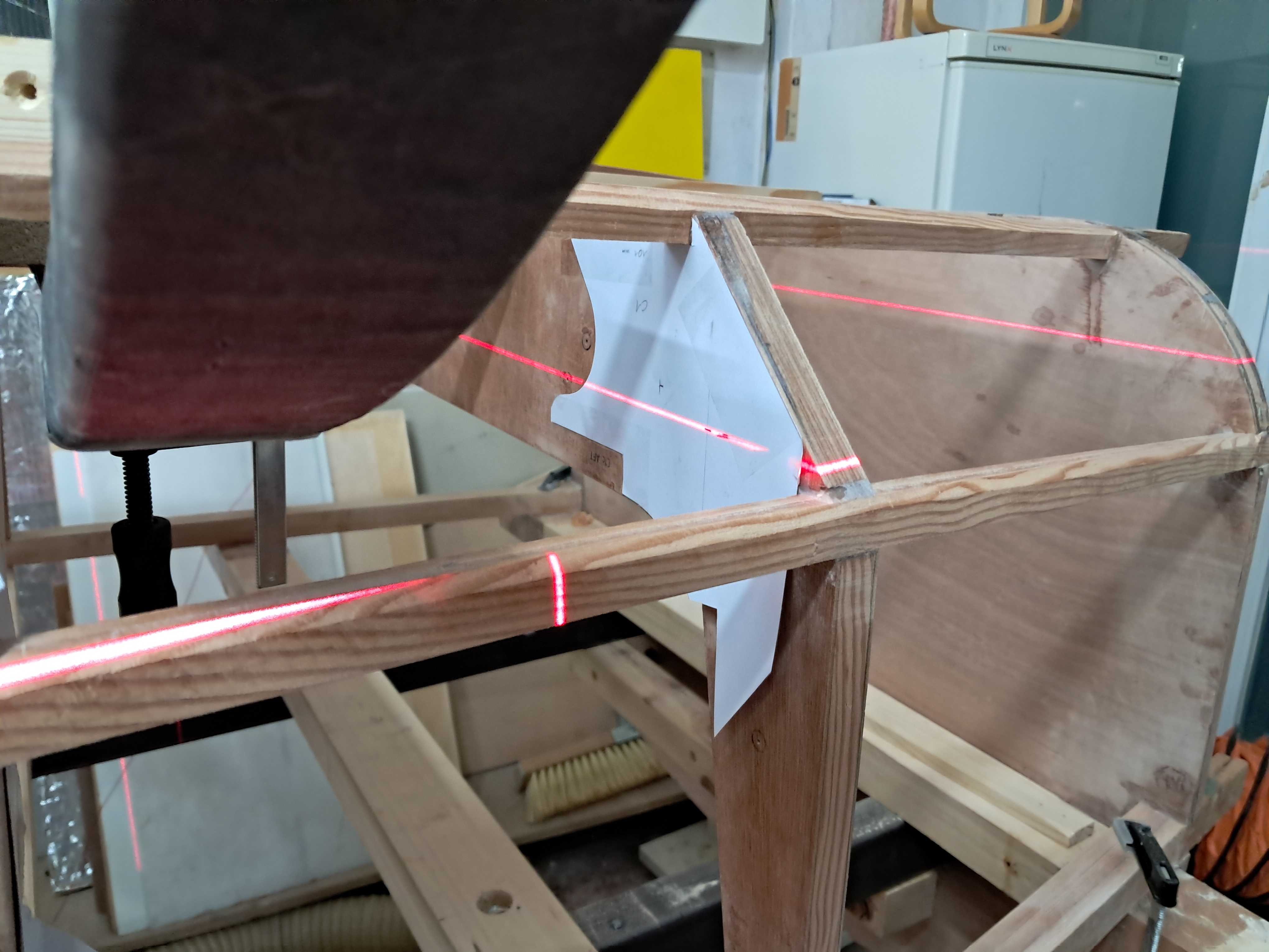
Cross-line laser projecting the pin axis across the frame and template.
×
Cross-line laser projecting the pin axis across the frame and template.
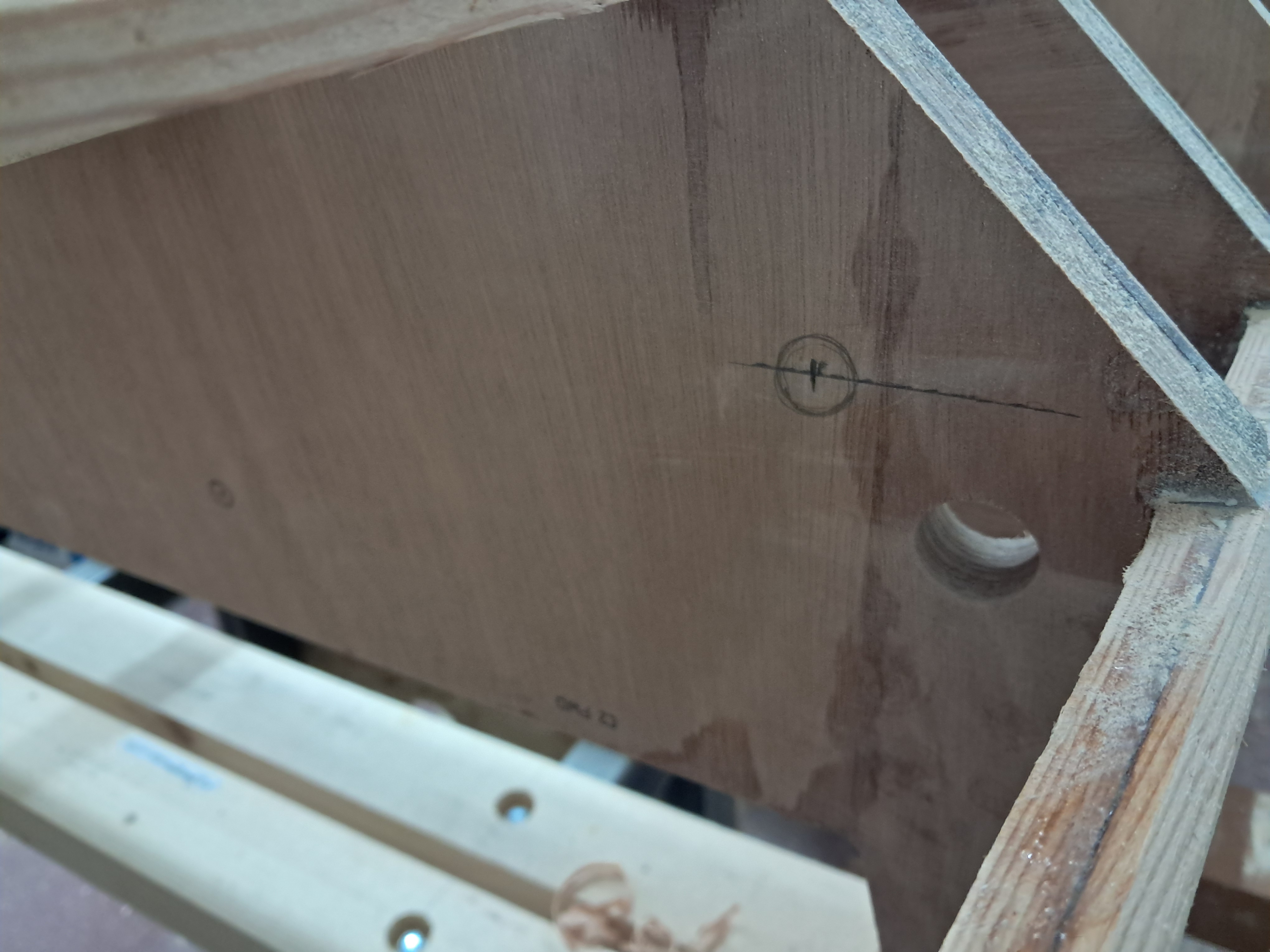
The hole center marked on the bulkhead, right in the corner where the bushing gets solid support.
×
The hole center marked on the bulkhead, right in the corner where the bushing gets solid support.
The marked center on the other bulkhead face.
×
The marked center on the other bulkhead face.
Template taped into the C1 corner with the pin hole marked.
×
Template taped into the C1 corner with the pin hole marked.
Overview at the end of the day: both templates in place at the bulkhead corners.
×
Overview at the end of the day: both templates in place at the bulkhead corners.
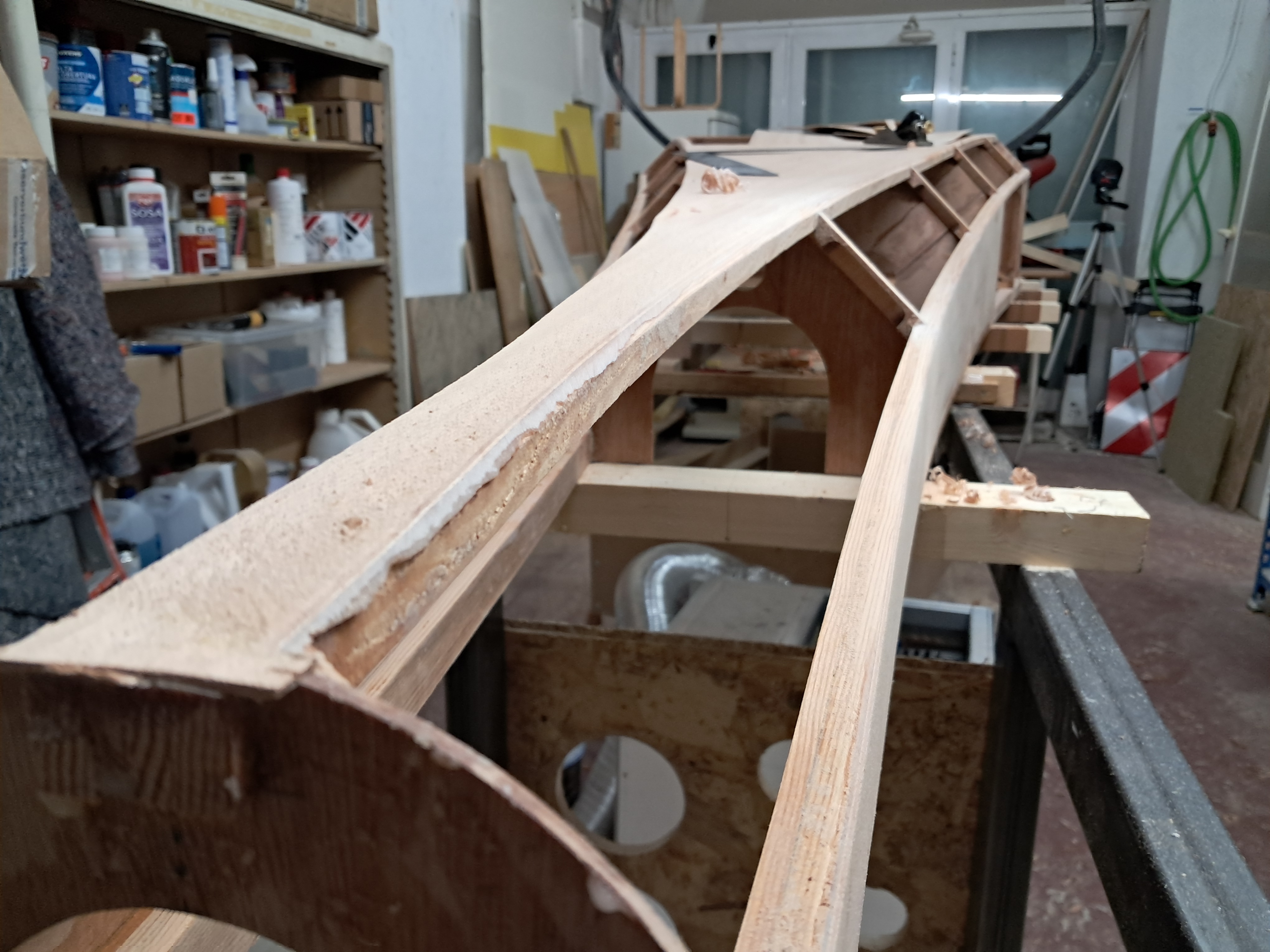
Sanding the 45 degree corners
Besides the landing gear pin location I also trimmed, planed and sanded the 45 degree corners of the
aft section. I am still not sure whether I have to redo the skin of the fuselage bottom. It is heavily
warped and I don't like it. The sides are much better. Of course it's wood and it will never be 100%
flat, but the bottom is really not good. I'll do a separate post about this.
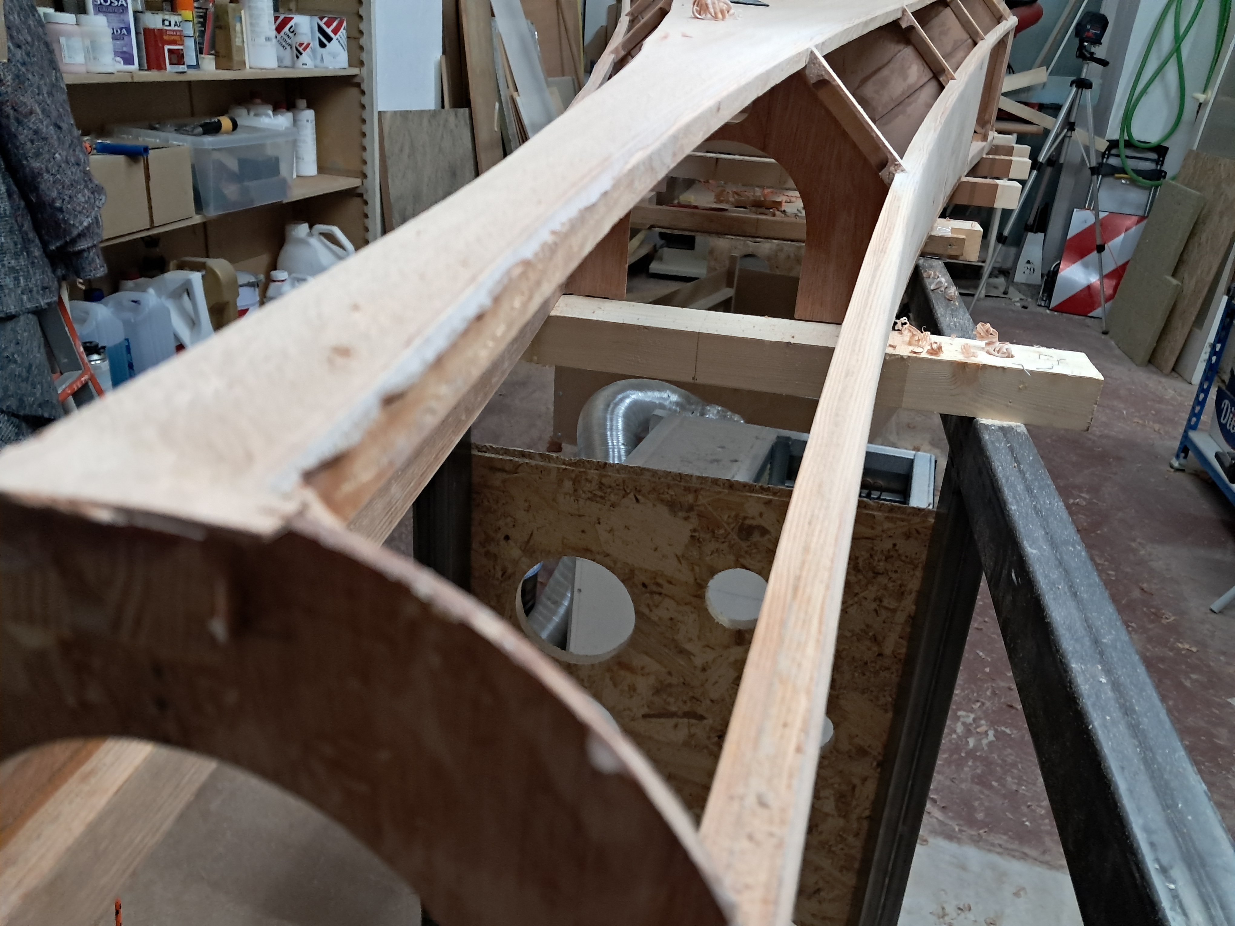
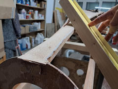
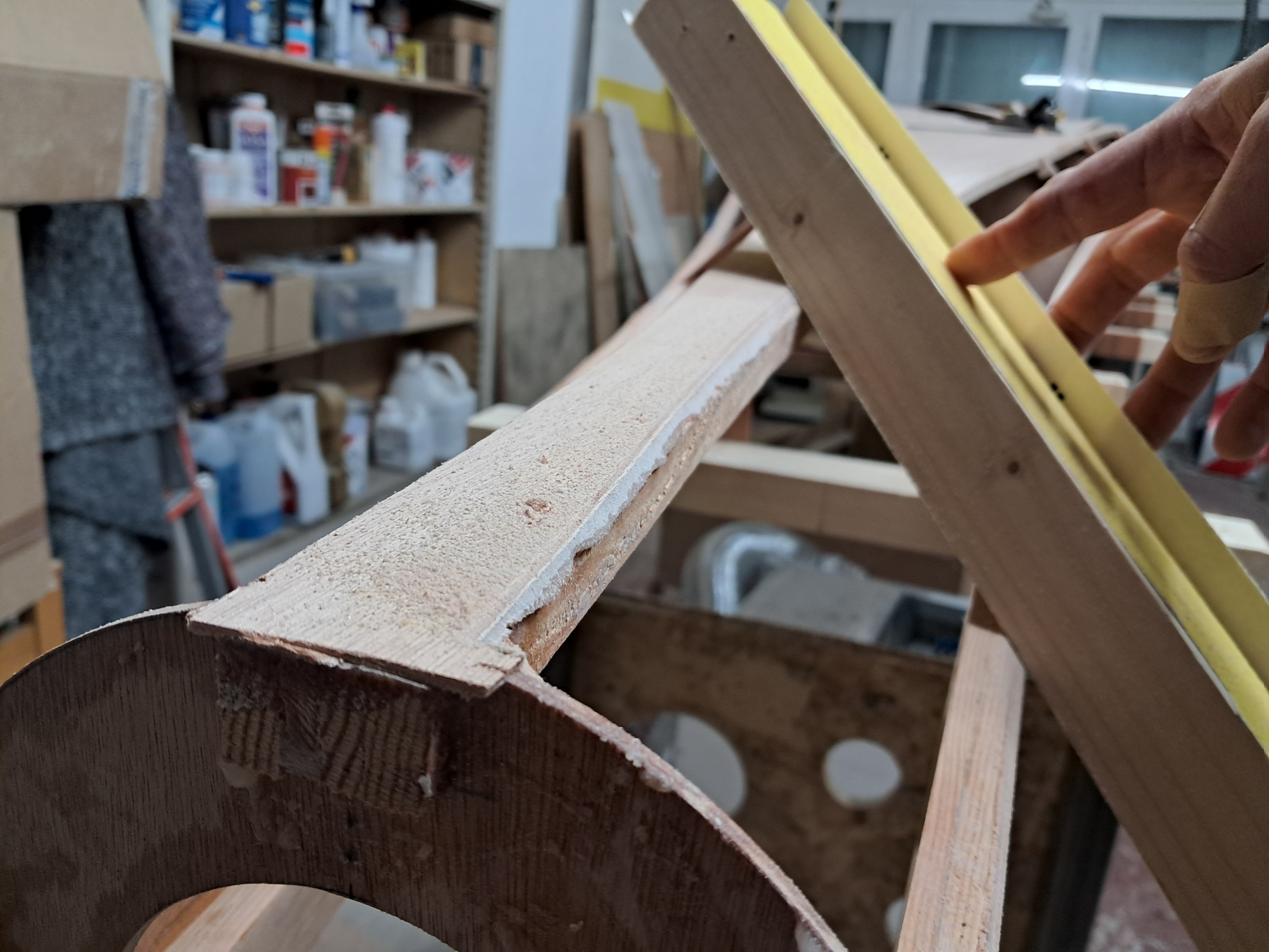
The 45 degree corner of the aft section after trimming and planing.
×
The 45 degree corner of the aft section after trimming and planing.
Looking aft along the planed corner; shavings still on the structure.
×
Looking aft along the planed corner; shavings still on the structure.
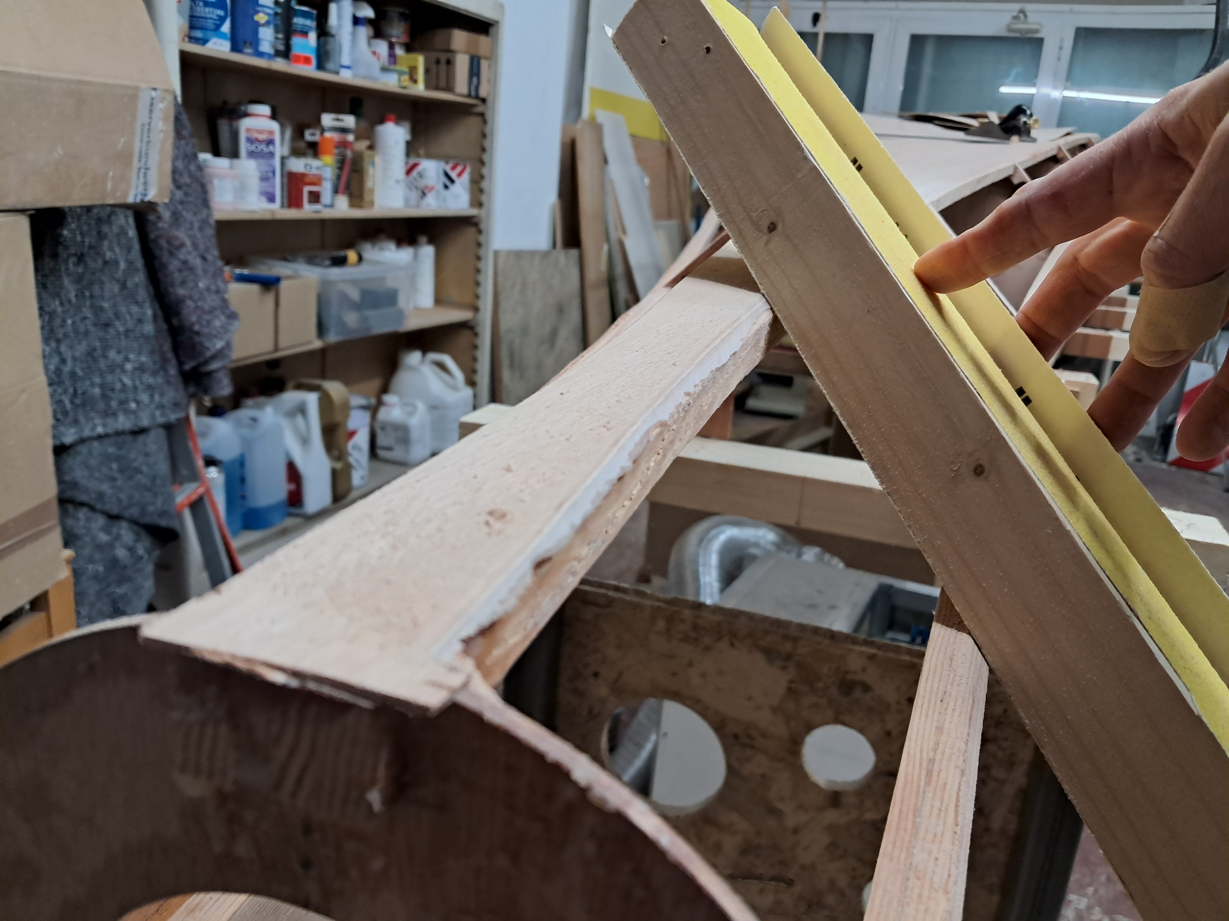
Checking the sanded 45 degree face with a straightedge.
×
Checking the sanded 45 degree face with a straightedge.
The corner face is flat; the skin will sit flush here.
×
The corner face is flat; the skin will sit flush here.