Today a friend CNC-machined the false spars for me. I was concerned that the version described in
the plans would not remain dimensionally stable enough over time to serve as a reliable template
when I eventually build the wings.
In addition, preparing the CAD model and having the parts machined was probably faster overall than
making the false spars manually.
The small notches along the upper edge, near the outer ends, were an attempt to be clever. The idea
was to place a 2 m straightedge or spirit level on them to level the assembly precisely, as shown in
the documentation. In the end, however, I did not use that feature.
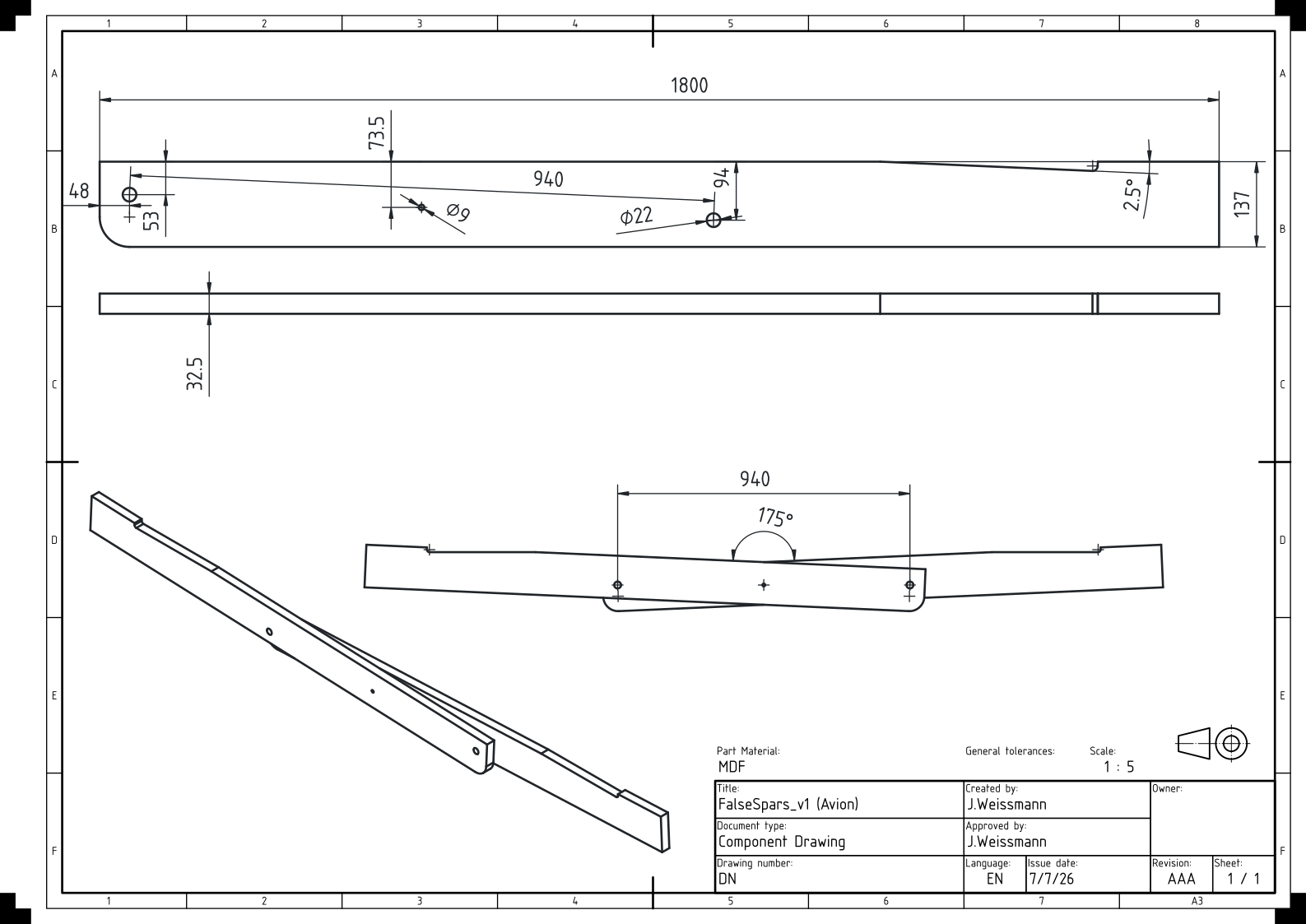
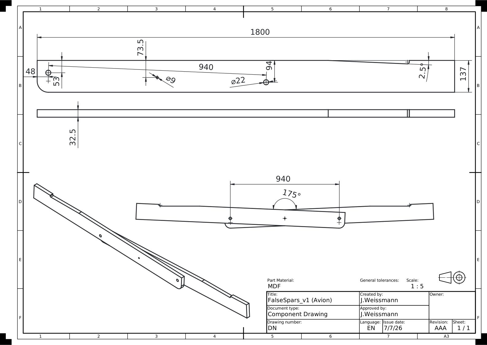
Drawing of the false spars. The two halves are aligned with 22 mm pins and set to a total included angle of 175 degrees.
×
Drawing of the false spars. The two halves are aligned with 22 mm pins and set to a total included angle of 175 degrees.
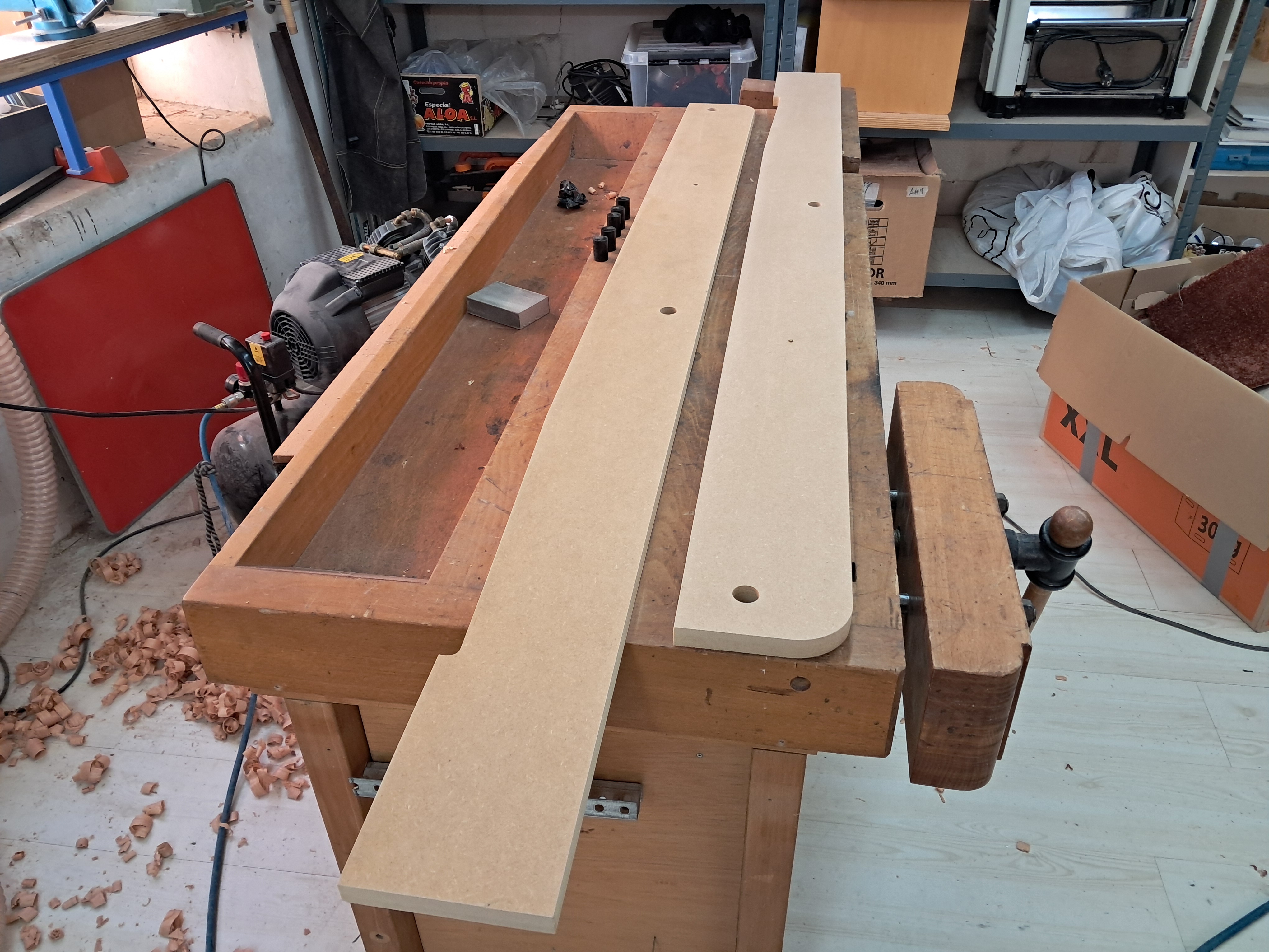
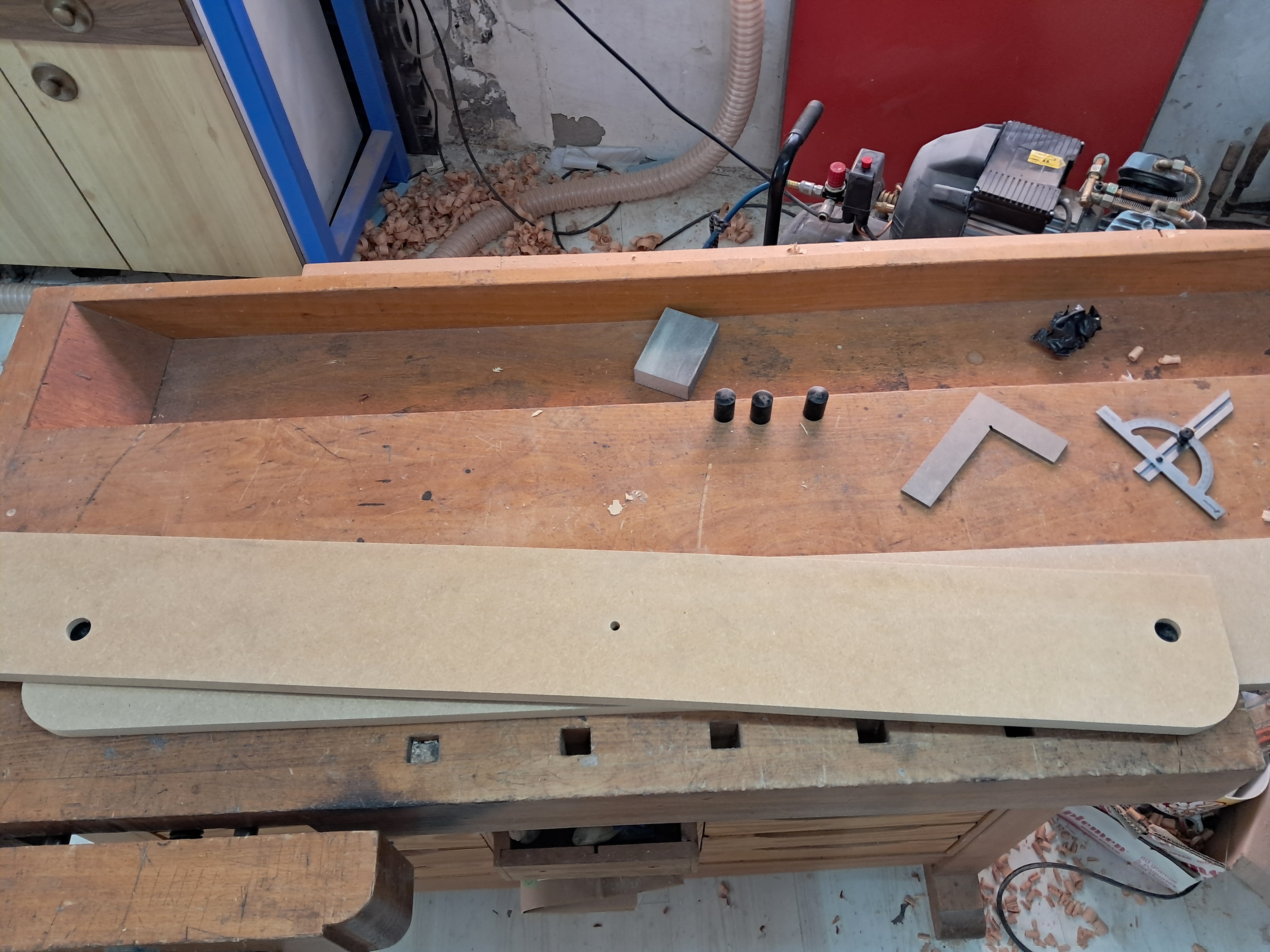
Both CNC-machined false spar halves on the bench.
×
Both CNC-machined false spar halves on the bench.
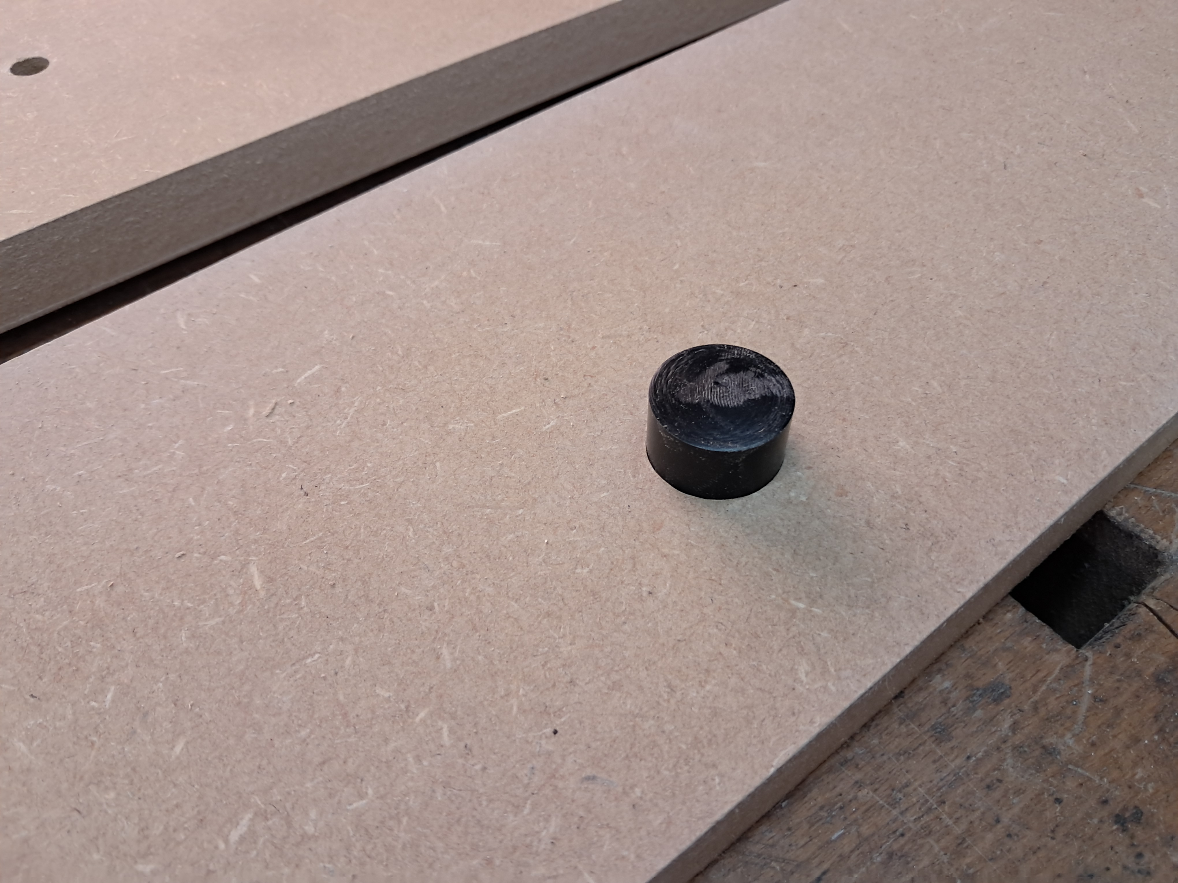
22 mm Delrin alignment plugs for locating the two false spar halves.
×
22 mm Delrin alignment plugs for locating the two false spar halves.
Both false spar halves aligned with the Delrin plugs.
×
Both false spar halves aligned with the Delrin plugs.
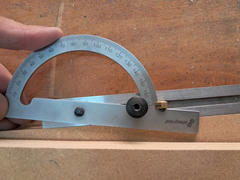
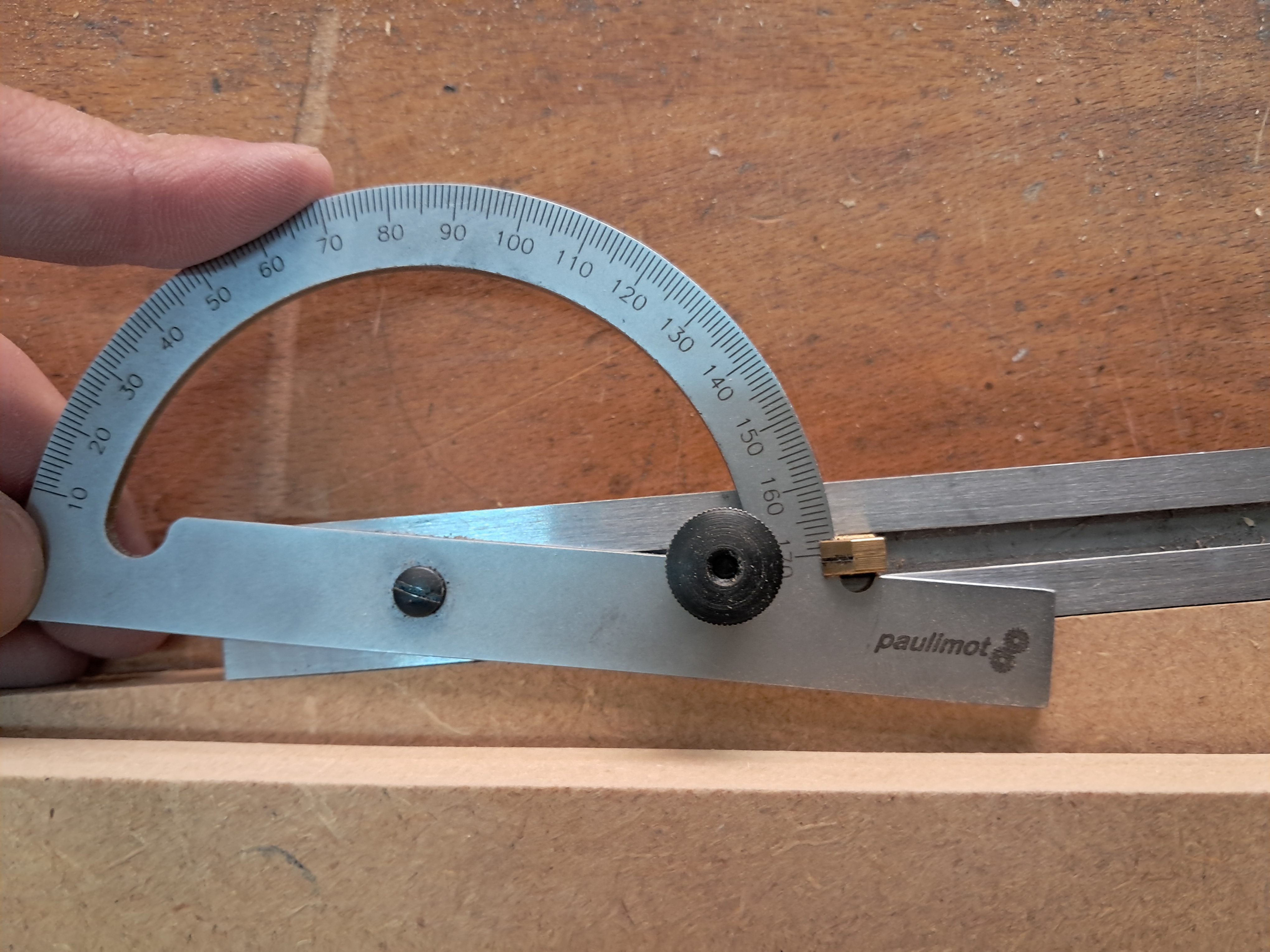
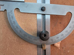
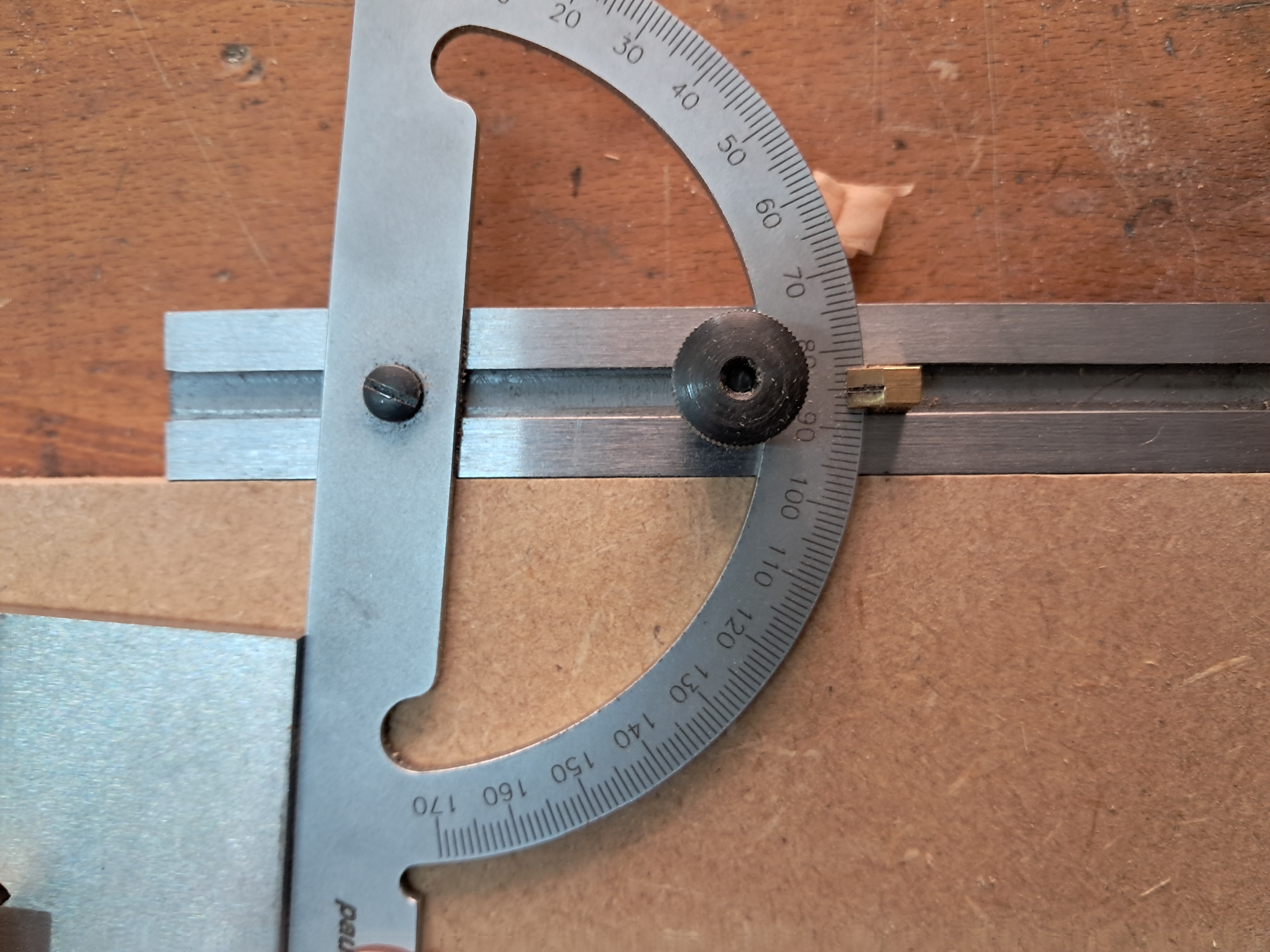
My angle gauge cannot resolve such small deviations very accurately. The target is 5 degrees total, i.e. 2 * 2.5 degrees.
×
My angle gauge cannot resolve such small deviations very accurately. The target is 5 degrees total, i.e. 2 * 2.5 degrees.
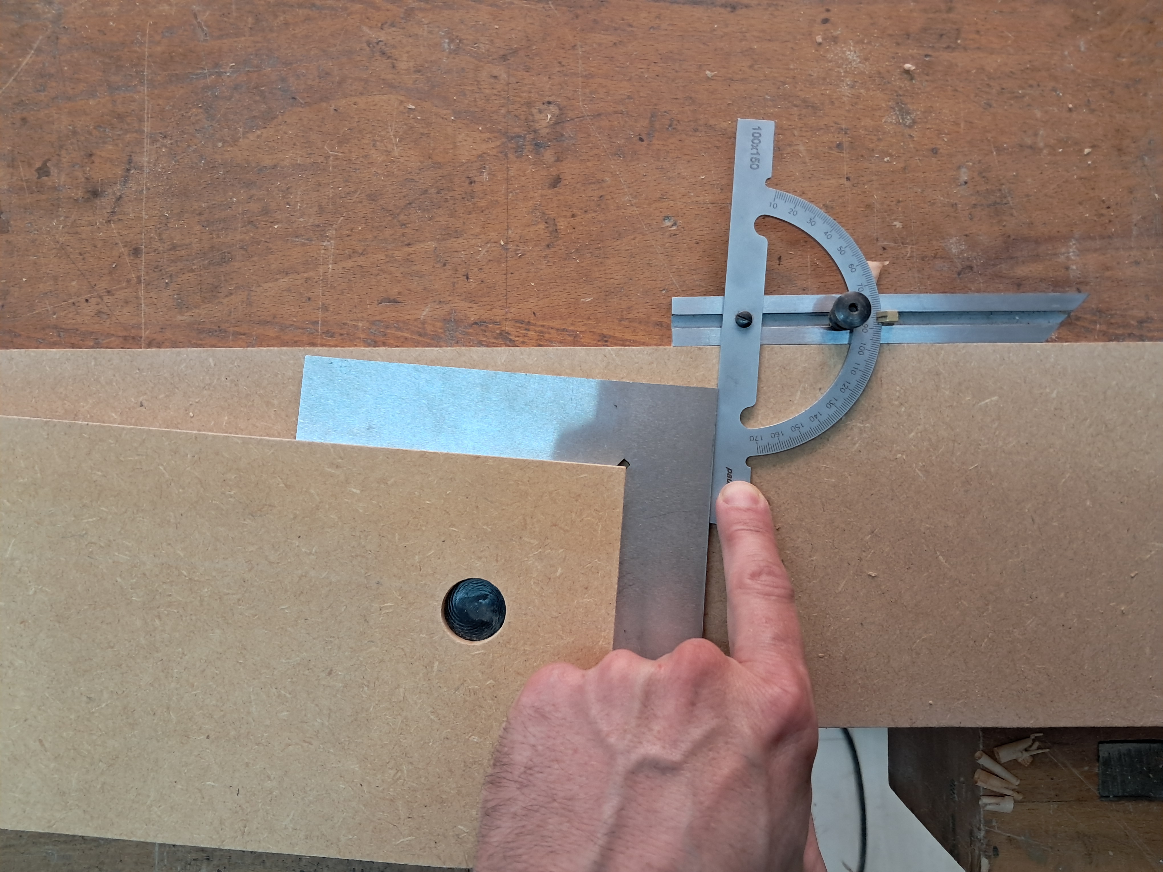
Checking the included angle between the two false spar halves.
×
Checking the included angle between the two false spar halves.
Final check of the angle: close enough for this temporary alignment fixture.
×
Final check of the angle: close enough for this temporary alignment fixture.
Next Steps
Next I have to finish fitting the 18x18 mm fuselage longerons before removing everything from the
strongback and drilling the holes for the wing attachment pins. Once those holes are drilled, I can
finally start bonding the fuselage structure together.